Interface
This document mainly introduces the driver control methods for GPIO/I2C/SPI/CAN/USB/UART interfaces.
GPIO
GPIO resource information:Jetson Orin NX Series and Jetson Orin Nano Series Pinmux
- Io extension panel interface hardware information
| Pin # | Signal Name | Description | Direction | Pin Type |
|---|---|---|---|---|
| 218 | GPIO12 | GPIO=Low/high when IN1=high(Open)/low(Short) | Input | dry contact |
| IN1_COM: COM pin | ||||
| 216 | GPIO11 | IN2: GPIO=Low/high when IN1=high(Open)/low(Short) | Input | dry contact |
| IN2_COM: COM pin | ||||
| 206 | GPIO07 | IN3: GPIO=Low/high when IN1=high(Open)/low(Short) | Input | dry contact |
| IN3_COM: COM pin | ||||
| 228 | GPIO13 | IN4: GPIO=Low/high when IN1=high(Open)/low(Short) | Input | dry contact |
| IN4_COM: COM pin | ||||
| 199 | I2S0_SCLK_1V8 | OUT1: GPIO=Low for short, high for open | Output | dry contact |
| OUT1_COM: COM pin | ||||
| 197 | I2S0_LRCK_1V8 | OUT2: GPIO=Low for short, high for open | Output | dry contact |
| OUT2_COM: COM pin | ||||
| 195 | I2S0_SDIN_1V8 | OUT3: GPIO=Low for shor, high for open. | Output | dry contact |
| OUT3_COM: COM pin | ||||
| 193 | I2S0_SDOUT_1V8 | OUT4: GPIO=Low for short, high for open. | Output | dry contact |
| OUT4_COM: COM pin |
- Find the corresponding line using the gpioinfo command
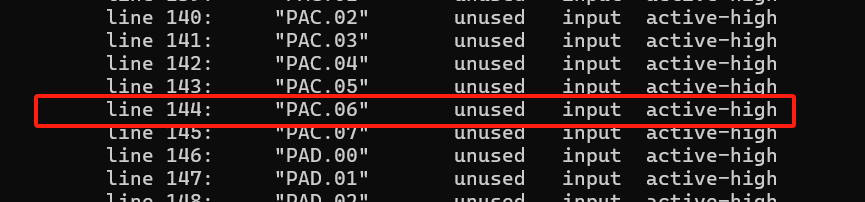
- Control GPIO using gpioset
# To set GPIO12 to HIGH
sudo gpioset --mode=wait gpiochip0 144=1
# To set GPIO12 to LOW
sudo gpioset --mode=wait gpiochip0 144=0
UART
| Usage on Orin nano/NX | UART Instance | Base Address | Ball Name | Bus Name | DTS status | DTS alias |
|---|---|---|---|---|---|---|
| Debug | UARTC | 0x0c280000 | UART2 | ttyTCU0 | OK | serial0 |
| RS485 | UARTA | 0x03100000 | UART1 | ttyTHS1 | OK | serial1 |
| RS232 | UARTB | 0x03110000 | UART0 | ttyTHS3 | OK | serial3 |
-
Debug
-
Hardware connection: Connect Debug cable to PC
-
Open serial tool with configuration: Baud rate: 115200, Data bits: 8, Stop bits: 1, Parity: None, Flow control: None
-
-
RS232
- Hardware interface information
Pin Signal Name Description Direction Pin Type 99 UART0_TXD Use for uart Ransmit (with 3.3 level shifter) Output CMOS – 1.8V 101 UART0_RXD Use for uart Receive (with 3.3 level shifter) Input CMOS – 1.8V -
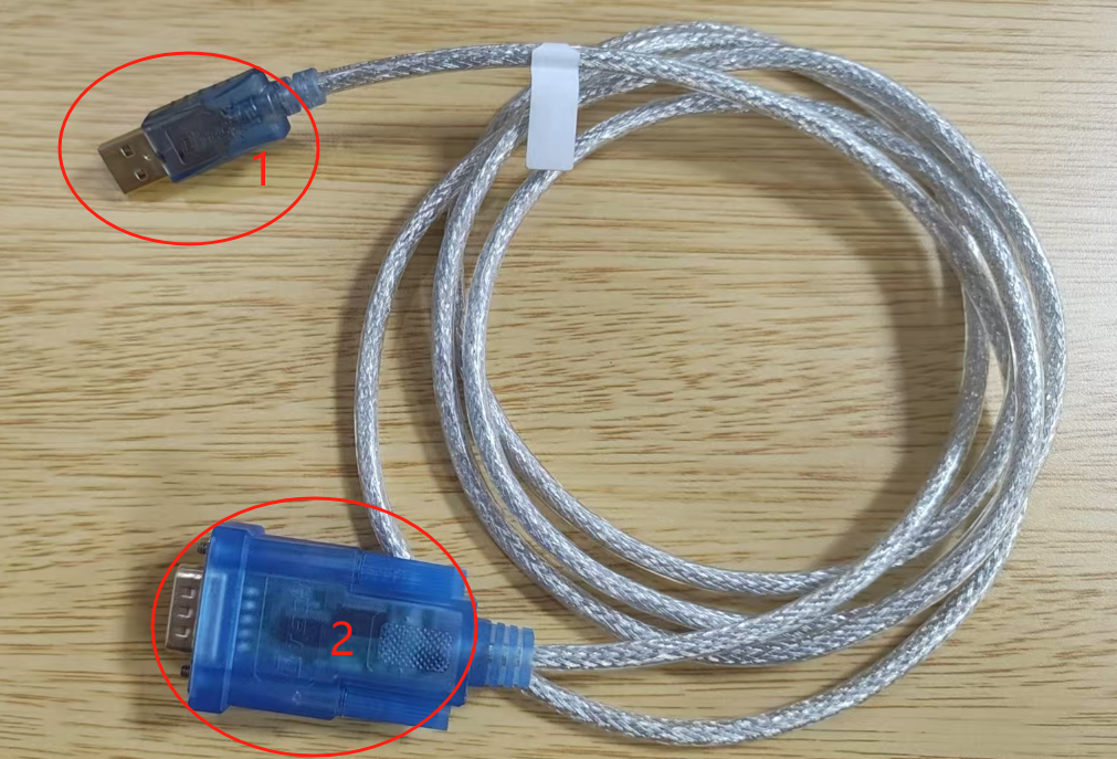
Hardware connection as shown below:
- Use connector 1 to connect to PC
- Use connector 2 to connect to Jetson's RS232
TX\RX
-
RS485
- Hardware interface information
Pin Signal Name Description Direction Pin Type 203 UART1_TXD Use for RS_485 Output CMOS 1.8V 205 UART1_RXD Use for RS_485 Input CMOS 1.8V 207 UART1_RTS* RS_485 enable pin Output CMOS 1.8V - Install dependency libraries
sudo apt-get update
sudo apt-get install gpiod libgpiod-dev- Compile
gcc -o rs485_test rs485_test.c -lgpiod- Run
sudo ./rs485_test [TTY_DIR] [DE_CHIP] [DE_LINE]
# Example
sudo ./rs485_test /dev/ttyTHS1 /dev/gpiochip0 112- Testing
Start the program, enter
sendin the terminal to switch to send mode, then enter the data to be sent and press Enter. The program will send the data to the serial port. Enterrecvto switch to receive mode, where the program will print received data. Enterquitand press Enter to exit. - Code
#include <stdio.h>
#include <stdlib.h>
#include <string.h>
#include <sys/stat.h>
#include <errno.h>
#include <unistd.h>
#include <fcntl.h>
#include <termios.h>
#include <gpiod.h>
#include <linux/serial.h>

#define BUFFER_SIZE 256
#define RS485_CONSUMER "RS485_program"

struct gpiod_chip *chip;
struct gpiod_line *rts_line;

void setup_gpio(char *gpio_chip, int gpio_line)
{
    int ret;

    chip = gpiod_chip_open(gpio_chip);
    if (!chip) {
        fprintf(stderr, "gpiod_chip_open");
        exit(EXIT_FAILURE);
    }

    rts_line = gpiod_chip_get_line(chip, gpio_line);
    if (!rts_line) {
        fprintf(stderr, "Failed to get GPIO line %d\n", gpio_line);
        gpiod_chip_close(chip);
        exit(EXIT_FAILURE);
    }

    ret = gpiod_line_request_output(rts_line, RS485_CONSUMER, 0);
    if (ret < 0) {
        fprintf(stderr, "Failed to request GPIO line as output: %s\n", strerror(-ret));
        gpiod_chip_close(chip);
        exit(EXIT_FAILURE);
    }
}

void set_rts_high() {
    gpiod_line_set_value(rts_line, 1);
    int value = gpiod_line_get_value(rts_line);
    printf("RTS set to HIGH, actual value: %d\n", value);
}

void set_rts_low() {
    gpiod_line_set_value(rts_line, 0);
    int value = gpiod_line_get_value(rts_line);
    printf("RTS set to LOW, actual value: %d\n", value);
}

int main(int argc, char* argv[]) {
    int tty_fd;
    char *tty_name;
    struct termios tty;
    char buffer[BUFFER_SIZE];
    ssize_t n;
    int ready;
    fd_set readfds;
    int rts_line_num;
    char *gpio_chip;
    int mode = 0;

    if (argc < 4) {
        printf("Usage: %s /dev/ttyTHS1 GPIO_CHIP(/dev/gpiochip*) RTS_LINE\n", argv[0]);
        return 1;
    }

    tty_name = argv[1];
    gpio_chip = argv[2];
    rts_line_num = atoi(argv[3]);

    setup_gpio(gpio_chip, rts_line_num);

    tty_fd = open(tty_name, O_RDWR | O_NOCTTY | O_NDELAY);
    if (tty_fd < 0) {
        perror("Unable to open serial port");
        return 1;
    }

    tcgetattr(tty_fd, &tty);
    cfmakeraw(&tty);
    cfsetispeed(&tty, B9600);
    cfsetospeed(&tty, B9600);
    tcsetattr(tty_fd, TCSANOW, &tty);

    printf("Serial port %s opened successfully, fd: %d\n", tty_name, tty_fd);

    while (1) {
        FD_ZERO(&readfds);
        FD_SET(tty_fd, &readfds);
        FD_SET(STDIN_FILENO, &readfds);

        ready = select(tty_fd + 1, &readfds, NULL, NULL, NULL);
        if (ready == -1) {
            perror("select");
            break;
        }

        if (FD_ISSET(tty_fd, &readfds)) {
            set_rts_low();
            n = read(tty_fd, buffer, BUFFER_SIZE - 1);
            if (n > 0) {
                buffer[n] = '\0';
                printf("Received: %s\n", buffer);
            }
        }

        if (FD_ISSET(STDIN_FILENO, &readfds)) {
            if (fgets(buffer, BUFFER_SIZE, stdin) != NULL) {
                buffer[strcspn(buffer, "\n")] = '\0';

                if (strcmp(buffer, "send") == 0) {
                    mode = 1;
                    printf("Switched to SEND mode\n");
                    continue;
                } else if (strcmp(buffer, "recv") == 0) {
                    mode = 0;
                    printf("Switched to RECEIVE mode\n");
                    continue;
                } else if (strcmp(buffer, "quit") == 0) {
                    break;
                }

                if (mode == 1) {
                    set_rts_high();
                    usleep(10000);
                    write(tty_fd, buffer, strlen(buffer));
                    tcdrain(tty_fd);
                    set_rts_low();
                } else {
                    printf("Invalid command in RECEIVE mode\n");
                }
            }
        }
    }

    close(tty_fd);
    gpiod_line_release(rts_line);
    gpiod_chip_close(chip);

    return 0;
}
SPI
- SPI hardware interface information
| Pin | Signal Name | Description | Direction | Pin Type |
|---|---|---|---|---|
| 106 | SPI1_SCK | SPI 1 Clock | Bidir | CMOS – 3.3V |
| 108 | SPI1_MISO | SPI 1 Master In / Slave Out | Bidir | CMOS – 3.3V |
| 104 | SPI1_MOSI | SPI 1 Master Out / Slave In | Bidir | CMOS – 3.3V |
| 110 | SPI1_CS0* | SPI 1 Chip Select 0 | Bidir | CMOS – 3.3V |
| 112 | SPI1_CS1* | SPI 1 Chip Select 1 | Bidir | CMOS – 3.3V |
-
Hardware connection: Short-circuit
MOSIandMISO -
Testing method:
# Get spi source code
git clone https://github.com/rm-hull/spidev-test
cd spidev-test/
gcc spidev_test.c -o spidev_test

#  Test
./spidev_test -v -D /dev/spidev0.0 -p "Test"
CAN
- Hardware interface information
| Pin | Signal Name | Description | Direction | Pin Type |
|---|---|---|---|---|
| 145 | CAN_TX | FD CAN Transmit | Output | CMOS – 3.3V |
| 143 | CAN_RX | FD CAN Receive | Input | CMOS – 3.3V |
-
Hardware connection: Connect D+ and D- between two devices
-
Install
can-utilstools
sudo apt update
sudo apt-get install can-utils
- Testing method
# Check can0 status and configuration
ip link show can0

# Configure can interface with bitrate 100kbps
sudo ip link set can0 up type can bitrate 100000

# On one device, listen:
candump can0

# On another device, send message through can0 interface:
cansend can0 123#11.22.33.44
RTC
- Modify RTC time
sudo hwclock --set --date="2000-01-01 12:00:00"
- Check RTC time
sudo hwclock -r
- Synchronize time
# System time → RTC
sudo hwclock --systohc

# RTC → System time
sudo hwclock --hctosys
- Check system time
date
- Network time synchronization
# If unable to set RTC, check if NTP service is running
# Disable NTP service
sudo systemctl stop systemd-timesyncd.service
sudo timedatectl set-ntp false
Camera
-
Methods for starting and configuring the camera module, using
imx219as an example. The hardware connection is as follows: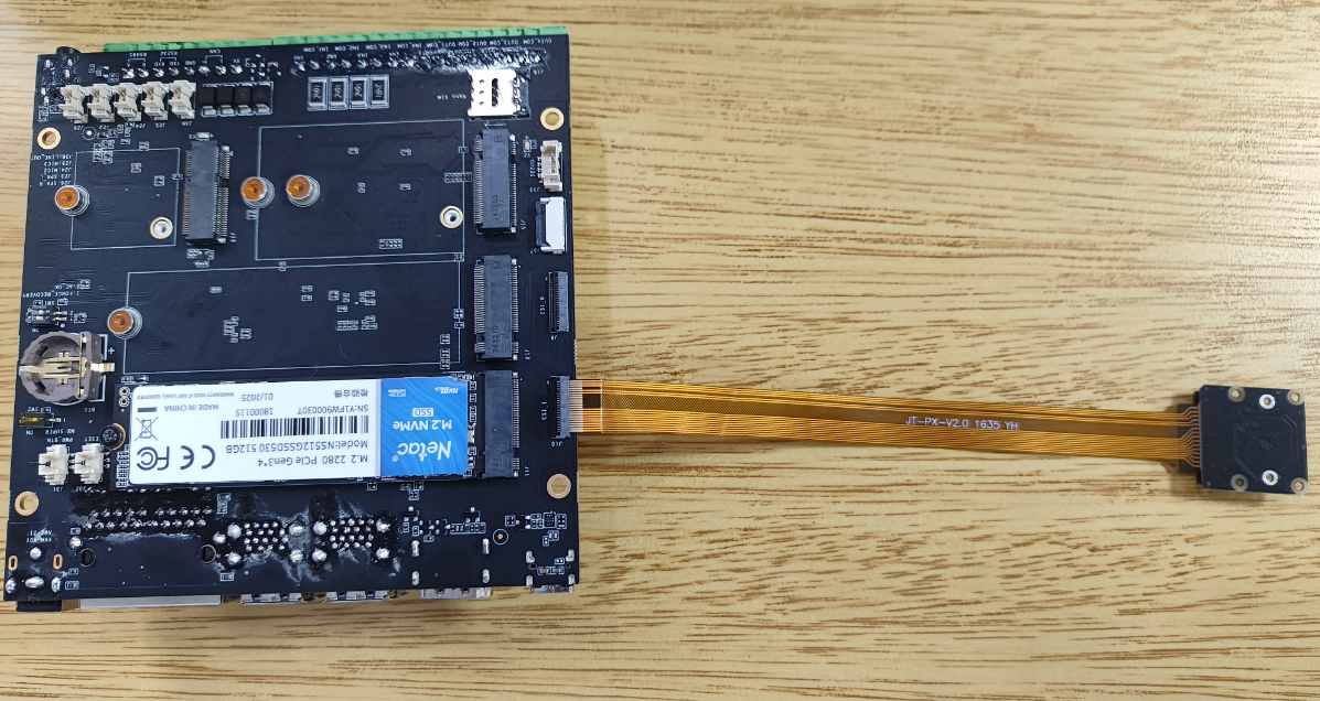
-
Start the camera using the config-by-hardware.py tool. The configuration will take effect after a reboot.
# List the currently supported hardware modules
sudo python /opt/nvidia/jetson-io/config-by-hardware.py -l
# Output example:
Header 1 [default]: Jetson 40pin Header
  Available hardware modules:
  1. Adafruit SPH0645LM4H
  2. Adafruit UDA1334A
  3. FE-PI Audio V1 and Z V2
  4. ReSpeaker 4 Mic Array
  5. ReSpeaker 4 Mic Linear Array
Header 2: Jetson 24pin CSI Connector
  Available hardware modules:
  1. Camera IMX219 Dual
  2. Camera IMX219 Dual CamThink
  3. Camera IMX219-A
  4. Camera IMX219-A and IMX477-C
  5. Camera IMX219-C
  6. Camera IMX477 Dual
  7. Camera IMX477 Dual 4 lane
  8. Camera IMX477-A
  9. Camera IMX477-A and IMX219-C
  10. Camera IMX477-C
Header 3: Jetson M.2 Key E Slot
  No hardware configurations found!

# Select and configure the IMX219 Dual CamThink camera module.
# -n selects the Header number, and Camera IMX219 Dual CamThink is the overlay-name of the dtbo.
sudo python /opt/nvidia/jetson-io/config-by-hardware.py -n 2='Camera IMX219 Dual CamThink'
- Connect a mouse and keyboard, open a terminal, and run the following commands:
sudo apt update
sudo apt install -y nvidia-l4t-gstreamer nvidia-l4t-jetson-multimedia-api

# Activate the camera
nvgstcapture-1.0